In the last episode, I had received the main parts of a Michelson Interferometer (the mirrors) and had roughly set them up using Lego stands. In the past couple of weeks I have been working on making a more stable and adjustable platform for this interferometer.
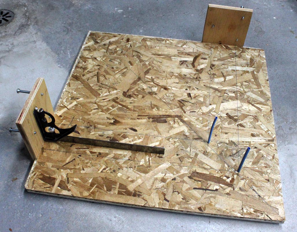
I decided to copy the main ideas of the interferometer at my school, so I bought a piece of chipboard flooring material from Home Depot, because floors are supposed to be strong and rigid, right? This piece of flooring also has Styrofoam insulation on the back that I thought would help isolate the platform from external vibrations. Keeping costs down, my basement provided a piece of scrap plywood that could be cut into two rectangles a bit bigger than the two front-surface mirrors. I cut grooves in them to match the “tongues” on the tongue-and-groove flooring. Then I drilled three holes in each so that I could mount nuts and bolts through the holes to adjust the position of the mirror. The nuts were glued in place. I sketched out the beam paths on the platform and then mounted the two mirror holders at the ends of the two perpendicular paths. Two long screws were put through from the back of the flooring to make a holder for the two-way mirror at 45 degrees to the two paths.
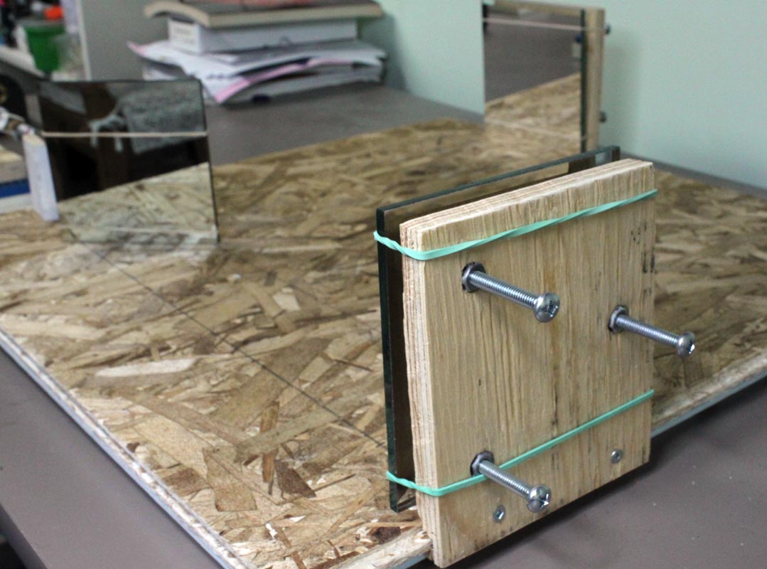
Elastic bands hold the mirrors to the mirror mounts, pressing the glass side of the mirrors against the tripod of the three bolts. Turning the bolts adjusts the angle of the mirror in three directions.
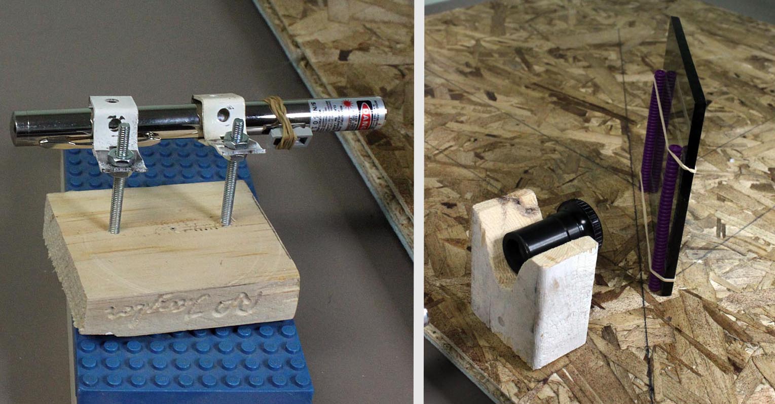
The other problem was to hold and adjust the laser and lens. For the lens holder, I just roughly cut an angle from a scrap block of wood. It holds a lens roughly halfway up the height of the mirrors, and can be used to hold a wide variety of lenses, depending on what’s available. I have a small, deeply curved plano-concave lens that works very well, but I discovered that a microscope eyepiece also works. It’s convenient to be able to move the lens around, but since it is at a fixed height, the laser must be mounted so that it can be moved vertically to match the lens. Again, a bit of scrap wood, a couple of nuts and bolts and some curtain rod holders did the job. Creative culch!
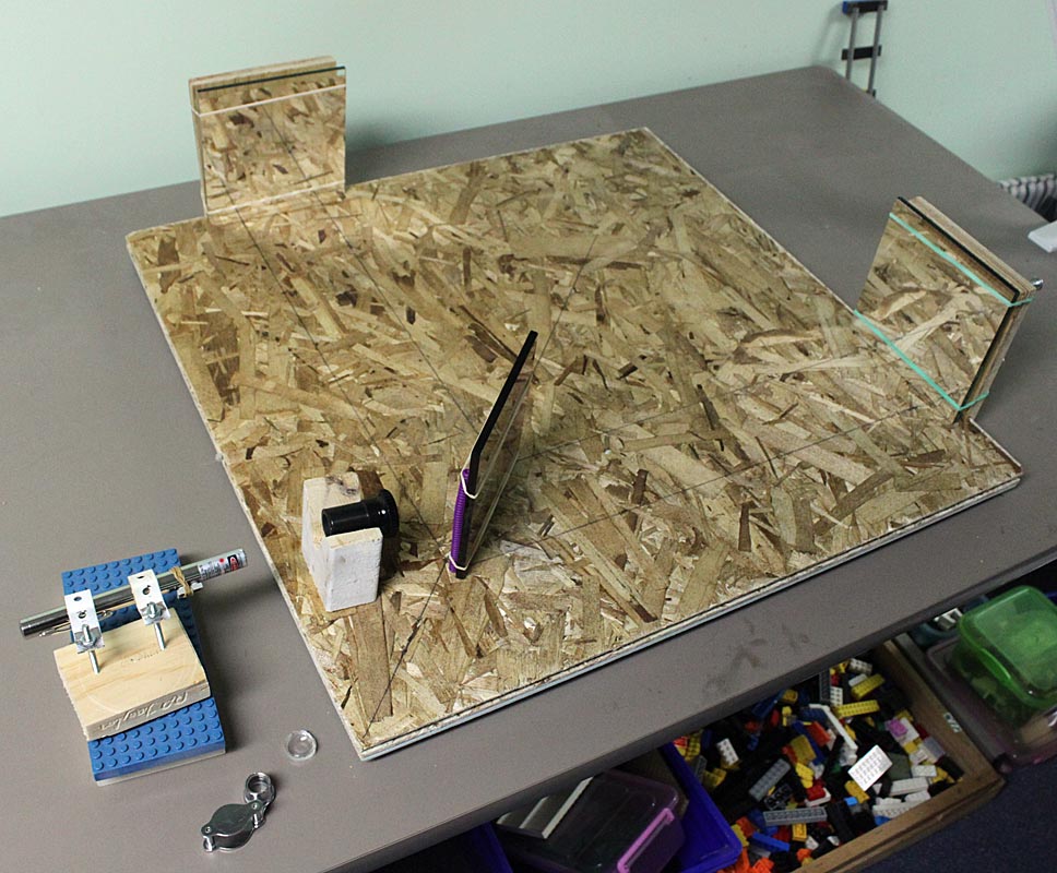
As you can see, I haven’t replaced ALL the Lego, yet!
So here’s the finished interferometer. Total cost: about $45 for the mirrors (but 2/3 of that was for the shipping, and I got an extra two-way mirror) and $7.70 for the piece of flooring makes $52.70. The other materials were scrap or extra materials from other projects. I’m sure any school with a wood shop would have similar. Laser pointers are pretty cheap these days, and most schools have some lasers available since they are useful for so many other optics experiments. As I said, a variety of beam-spreading lenses can be used, including borrowing one from a microscope.
The adjustments of the beams and mirrors is still quite tricky, so I have made a video of the process.
Here are the main steps:
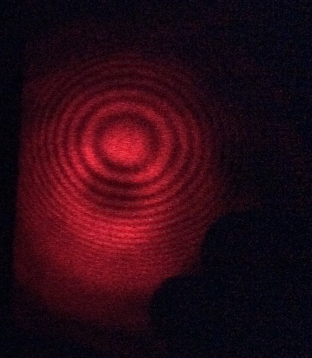
1. Make sure everything is roughly aligned as shown in the photo above, making sure that the laser’s beam is vertically aligned with the center of the lens, and when the lens is removed, the laser beam roughly follows the two paths, then recombines. 2. Place a white screen (piece of paper) about a meter away on the path that is perpendicular to the original path of the laser. You should see two or three bright dots on this screen that move when you adjust the bolts behind the mirrors. I saw one bright dot caused by the reflections off the front surface of the two-way mirror and two other fainter dots caused by the reflections from both the glass and the back surface of the two-way mirror. 3. Adjust the laser and the bolts behind the mirrors so that the laser beam and its reflections are passing approximately through the center of the two-way mirror, then carefully adjust the bolts so that the two brightest dots are on top of each other. 4. Put the lens into the beam path, and move it around until the larger circle of light is about in the same place on the screen as where you saw the dots. You may have to adjust the position and angle of the laser as well to make this happen. Keep still and allow the system to settle. If you are lucky, you should see some light and dark interference bands in the circle of light on the screen. They may be VERY close together and they will change rapidly if there is any disturbance to either of the two paths. 5. Look carefully at the interference bands and see if you can tell where they are closest and where they are farther apart. Adjust one of the mirror bolts, let things settle and see if the bands are even farther apart. If they are, keep adjusting that screw in the same direction, if they are closer together, try the opposite direction or another bolt. You are trying to find the center of a bulls-eye pattern like this:
Breaking news! My most recent experiment was to replace the two-way mirror with an ordinary piece of glass from a picture frame. The pattern was fainter, but it worked!