Dave Doucette (OAPT President) Richmond Hill High School, Richmond Hill, Ontario
Several years ago I was in need of a cheap, easily assembled, sensitive magnetometer. The intent was to design a tool for students to palpably observe the magnetic field around a current carrying conductor. Deflection of a compass needle lacked the ‘wow factor’ I sought. The solution turned out to be beautiful in its simplicity.
A plastic petri dish is the central component, consisting of a circular bottom dish with a slightly wider dish acting as the lid. Begin by taking the top dish and sitting it flat, like a tiny swimming pool. Fill it nearly to the brim with water (place the dish on a paper towel for spillage). The bottom dish is then floated on top of the water-filled top plate. A small wooden stick, with a wafer magnet hot-glued on each end, is set across the centre of the top dish so that it balances easily. Give this a tiny torque and it should spin freely without the edges grinding. Adjust the amount of water and the position of the wooden stick until friction is essentially eliminated. You now have a sensitive (qualitative) magnetometer (Fig. 1). Any standard magnet can be used to gauge the sensitivity.
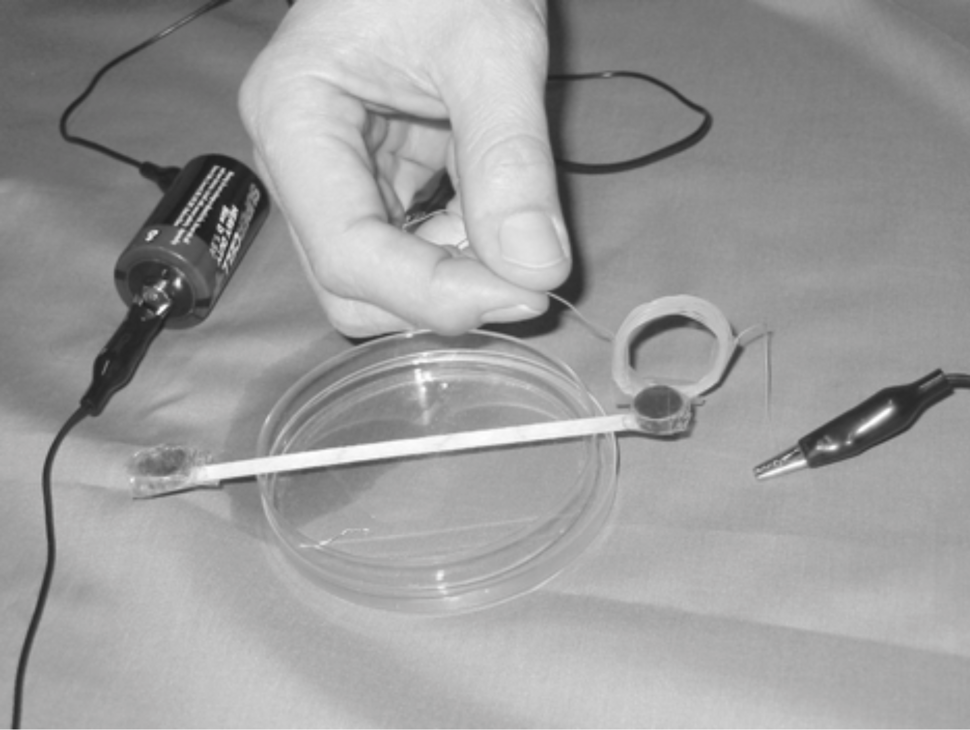 Figure 1: A coil of wire (10 windings) is held near one of the wafer magnets glued to the wooden stick. This causes the dish/stick assembly to rotate, depending on the position of the coil, direction of current, and wafer polarity.
Students first test a disconnected wire for magnetism — this gives a null result. Then they attach the wire leads to the terminals of a 1.5-V battery. The wire should be stretched flat and held directly overtop one of the wafer magnets. The orientation of the wire is critical. When placed parallel to the wooden stick, and directly over one wafer magnet, the resulting rotation of the dish/stick apparatus is maximized
1. The rotation is reversed by switching the leads. The alligator clip ends of the wire need to be kept away from the wafer magnets, as the steel leads are magnetic.
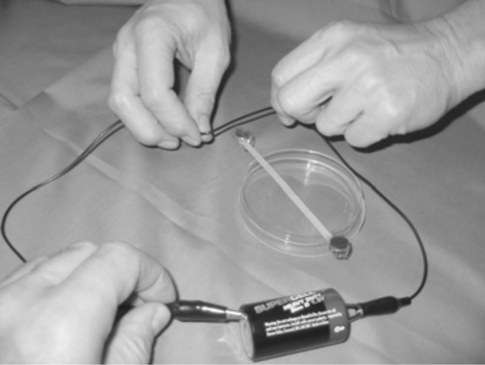 Figure 2: The conducting wire, when perpendicular to the wooden stick, produces zero torque but causes the stick/magnet assembly to accelerate linearly. This halts quickly as the petri dishes make contact.
When the wire is perpendicular to the stick (Fig. 2), but still directly above a wafer magnet, the rotation is zero. In this case the magnetic force is directed along the long axis of the stick, and careful observation will reveal the entire assembly to accelerate linearly for a brief time, halting when the floating dish butts against the bottom dish.

Students can coil up the wire to see the notable increase in attraction or repulsion. By “flipping” the coil, they begin to visualize the coil’s N-S magnetic polarity, mimicking the magnetic field about the wafer magnet. A ceramic magnet can be substituted for the coil to underscore this similarity.
Teachers can scaffold this activity into the SPH3U
electromagnetism unit. The new curriculum emphasis on inquiry learning would support a minimal introduction, if any, and an opportunity for students to present whiteboard observations and explanations to their peers. It would be a simple matter for class groups to try wires and coils and list a series of observations. Each group could then select a different observation to explain. As discussions ensue, groups should be free to modify their explanations. This mirrors the fluid, provisional nature of science modeling and reinforces the student-centred instructional approach recommended on page 31 in the
2008 11/12 Ontario Science Curriculum:
“A much more effective way to learn is for students to be actively involved in thinking and discussing during both class and investigation activities, with the goal of having the students develop a deep understanding of scientific concepts.” 2Endnotes
1 The force on a charge
q moving with velocity
v in the wire in the magnetic field
B above the wafer magnet is given by the vector cross product
F =
qv ×
B . The magnetic field above the magnet is essentially vertical, and since
v is along the direction of the horizontal wire, the direction of the force on the wire will also be horizontal but perpendicular to the wire. Therefore, when the wire is parallel to the stick, this force will be perpendicular to both the wire and the stick. By Newton’s third law of motion, the force on the magnet (and attached stick) will be in the opposite direction to the force on the wire. Thus, the force on the magnet is also perpendicular to the stick and this force provides a torque that rotates the stick/magnet assembly.
2 Kathleen Falconer et al.,
Effect of Reformed Courses in Physics and Physical Science on Student Conceptual Understanding (American Educational Research Association, April 2001, p1).
Column Editor: Ernie McFarland, Physics Department, University of Guelph, Guelph, Ontario, N1G 2W1 Tags: Field Theory, Magnetism