A Not-so-Serious Parallel Circuit
January 01, 1992 Filed in:
Demo CornerPeter Zuech, Mother Teresa S.S., Scarborough
This idea was born while watching the Tonight Show. A popular entertainer demonstrated a wooden board upon which four coloured light bulbs in sockets were mounted along with a corresponding set of four coloured switches. No matter how the bulbs were rearranged in the sockets, the blue switch turned the blue bulb on and off, the red switch operated the red bulb, and so on. Johnny examined the bulbs, found them to be “normal” and was convinced that it was magic. Unable to determine how the four-bulb unit operated, we designed a simpler two-bulb version for use as a discrepant event in current electricity. Our unit used two white bulbs but coloured ones could be used as in the original unit. The only skills required to construct the unit are an ability to solder and the willingness to tinker a little.
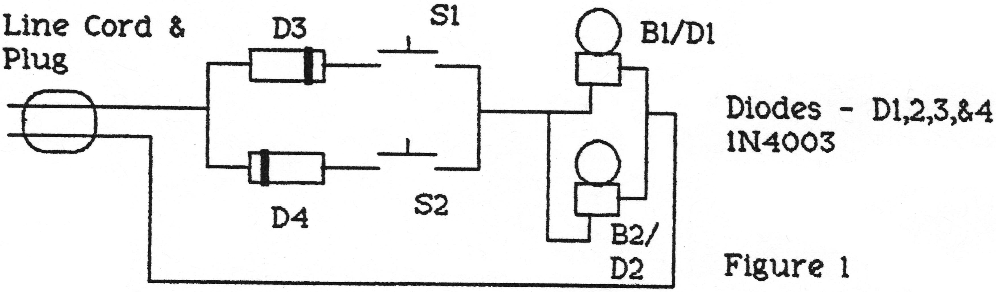
Figure 1 shows the circuit diagram of the setup. Ordinary household 40 W bulbs (modified as described below) are used. The bulb sockets are standard flush mounting fixtures and the switches Si and S2 are normal momentary-contact push buttons (rated for 120 V AC). The entire assembly is mounted on a small piece of plywood with the switches and sockets visible on the front and the wire and diodes D3 and D4 hidden on the back.
Diodes D1 and D2 are placed inside the base of the light bulbs B1 and B2 by first removing the centre contact on the bulbs using a disk sander. Once the metal is removed, the insulation is chipped away leaving one of the filament leads free. The other end of the filament remains attached to the threaded base of the bulb. The diodes in the bulbs are connected with their banded ends (cathodes) in opposite directions and pushed into the space inside the base. Be careful not to have any wires touch in the base when crowding everything in. Use a glue gun to fill the base and hold the leads in place so that only the free lead of the diode sticks out from the end of the bulb. Solder a brass washer to this lead to form the new centre contact of the bulb. Using more glue, put the washer in the centre of the base and restore the cone-shaped appearance of the insulator. Colour the visible glue with a black marker to further disguise your work.
Because of the orientation of the diodes, only one bulb will light up when the switches are closed one at a time. The alternating current will flow in only one direction through the switch, and only the bulb with its diode in the same orientation as that in the switch path will light. In order to throw a further red herring into the demonstration, put false wires on the front of the plywood which would lead the students to believe that the components are connected in a normal series/parallel circuit.
One way to introduce the demonstration is to start with the bulbs inserted in the opposite sockets. After an embarrassed pause, “fix” the circuit by switching the bulbs around, show surprise at the result, and ask for an explanation. Students will probably ask you to try the bulbs in different sockets and to close different combinations of the two switches. You can explain the operation of the circuit by drawing the diagram of the connections, stating that the sockets are electrically identical, and explaining that the alternating current can only flow through the diodes in one direction.
This demonstration can be used in a Grade 12 Advanced Physics class to stimulate interest and in technology or electronics classes to illustrate the concept of the diode as a one-way electrical valve.
Column Editor: Ernie McFarland, Physics Department, University of Guelph, Guelph, Ontario, N1G 2W1 Tags: Electricity