Arnold Arons (1979)
About the Author
My name is Eric Haller. I’m a new teacher and I am currently at the start of my third year teaching in China. Even though I live so far away, I was able to make it to the physics camp in Sudbury two summers ago. There I got a book called FIVE EASY LESSONS: Strategies for Successful Physics Teaching by Randall D. Knight, which I highly recommend. In this book, Knight talks about many different ways we can improve how we teach physics, a few of which I’ve actually tried out with my students. I want to share with you one of the successes I’ve had with those strategies, here is how I teach my students to draw system and free body diagrams.
How to Draw System Diagrams
Step 1
Draw a simple sketch of the situation
Try to keep the picture simple, use stick men, and three dimensions only if necessary. Make sure you include important things like the ground, ropes, springs and so forth.
Step 2
Draw a closed curve around the object of interest
This curve is rarely a circle; it should hug the object close where necessary. For example, suppose a tow truck is pulling an old car by a rope. If you’re interested in the car, draw a curve around the entire car, but make sure the ground, the rope, and the tow truck are not within the curve. I like to label everything inside the curve as “the system” and everything outside as “the environment”. Later on when you talk about internal and external forces, this helps to distinguish between the two.
Step 3
Label every contact force by name, and identify the two objects the force is between
Contact forces may exist where the system meets the environment and they occur along the boundary curve from step 2. From before, the rope is in contact with the car so we would label that as a tension force of the rope acting on the car. The car is also pulling on the rope (Newton’s third law), but since that force is not acting on the system, we don’t need to worry about it. Some points of contact have more than one contact force present there. For example, the point of contact between the tires of the car and the ground should be labelled as a normal force of the road acting on the car and a force of friction of the road acting on the car.
Step 4
Label every non-contact force by name, and identify the two objects the force is between
Gravity does not require any contact with the system, so don’t mention it along the boundary curve. Instead, write an aside saying that there is a force of gravity of the Earth acting on the car. Later you can introduce electromagnetic forces this way as well.
Here is what the system diagram of a car being towed by a truck should resemble. You should notice how there are no arrows at all in the system diagram.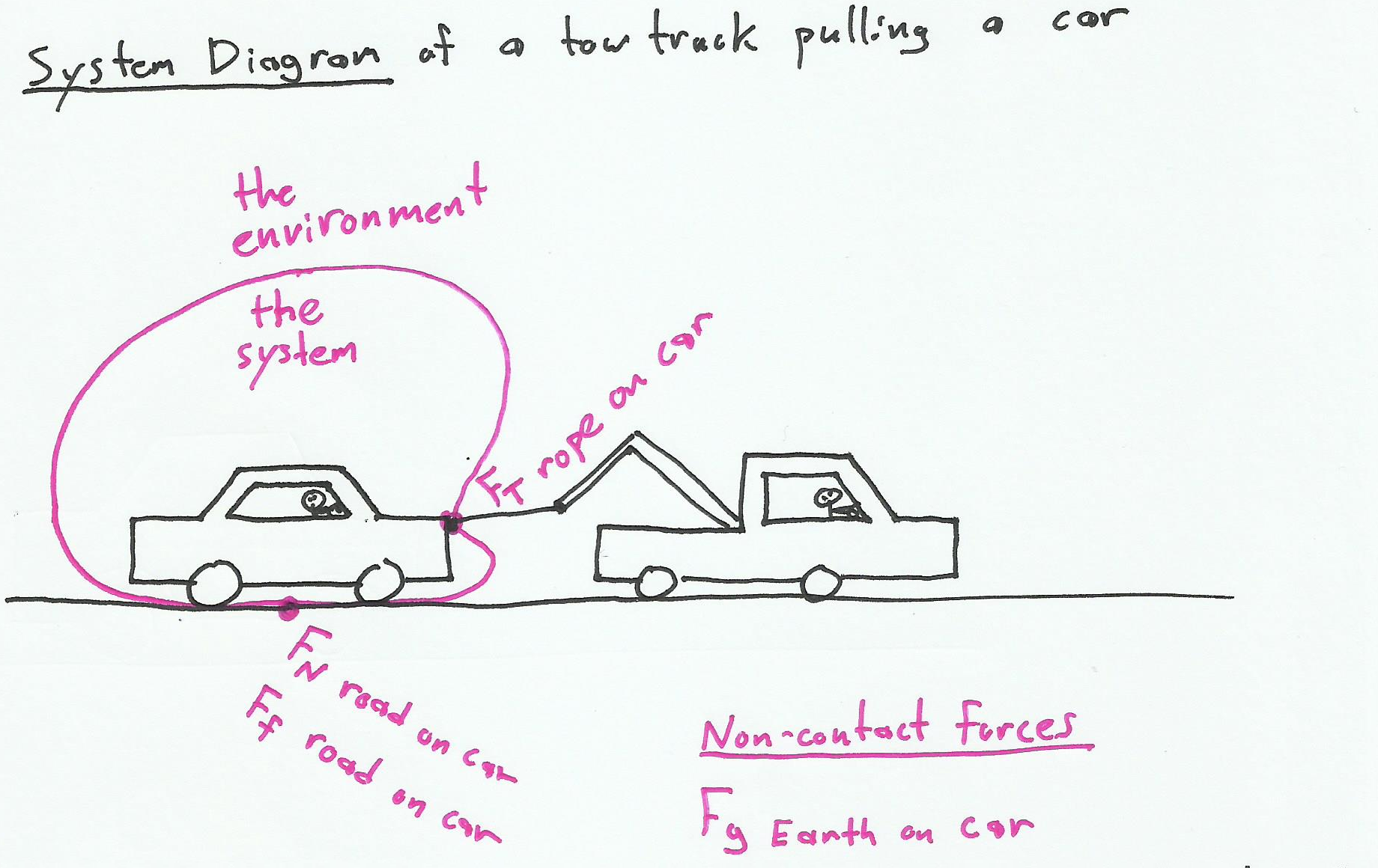
How to Draw Free Body Diagrams
Step 1
Draw a dot
This dot is very important, it should actually only be a simple dot on a page. This dot represents “the system”. If every student draws just a dot, it makes everyone’s diagrams look the same, and makes them much easier to decipher on a test. Also, if a porcupine gets shot with arrows, at least the porcupine is now only a dot.
Step 2
Draw an arrow, outwards from the dot, representing each force mentioned in the system diagram. Try to draw them in the direction of the force, and try to draw them to scale with each other. Label each force
If a car is being pulled to the right by a rope, the arrow for this force should be on the right side of the dot going away from the dot, and not on the left side of the dot going towards the dot. Of course both would have the same meaning, but it’s easier to analyze the system if all the dots originate from the centre of the dot. Even more important is that students only draw forces that are mentioned in their system diagrams, no additional forces are allowed and none of those forces should be left out either.
Here is what the free body diagram of a car being towed by a truck should resemble.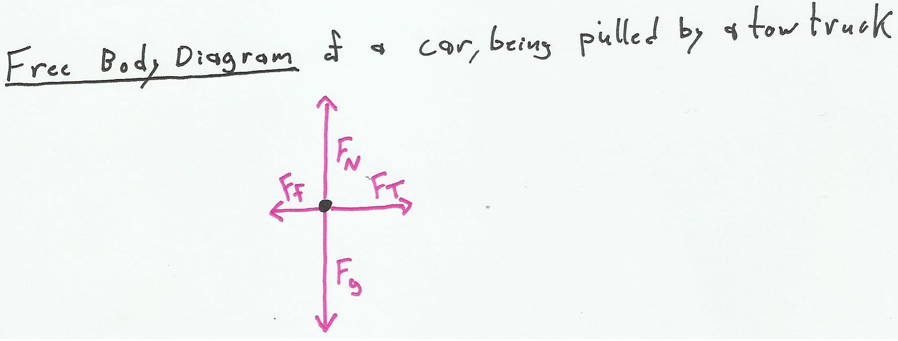
Why I Draw System and Free Body Diagrams Like This
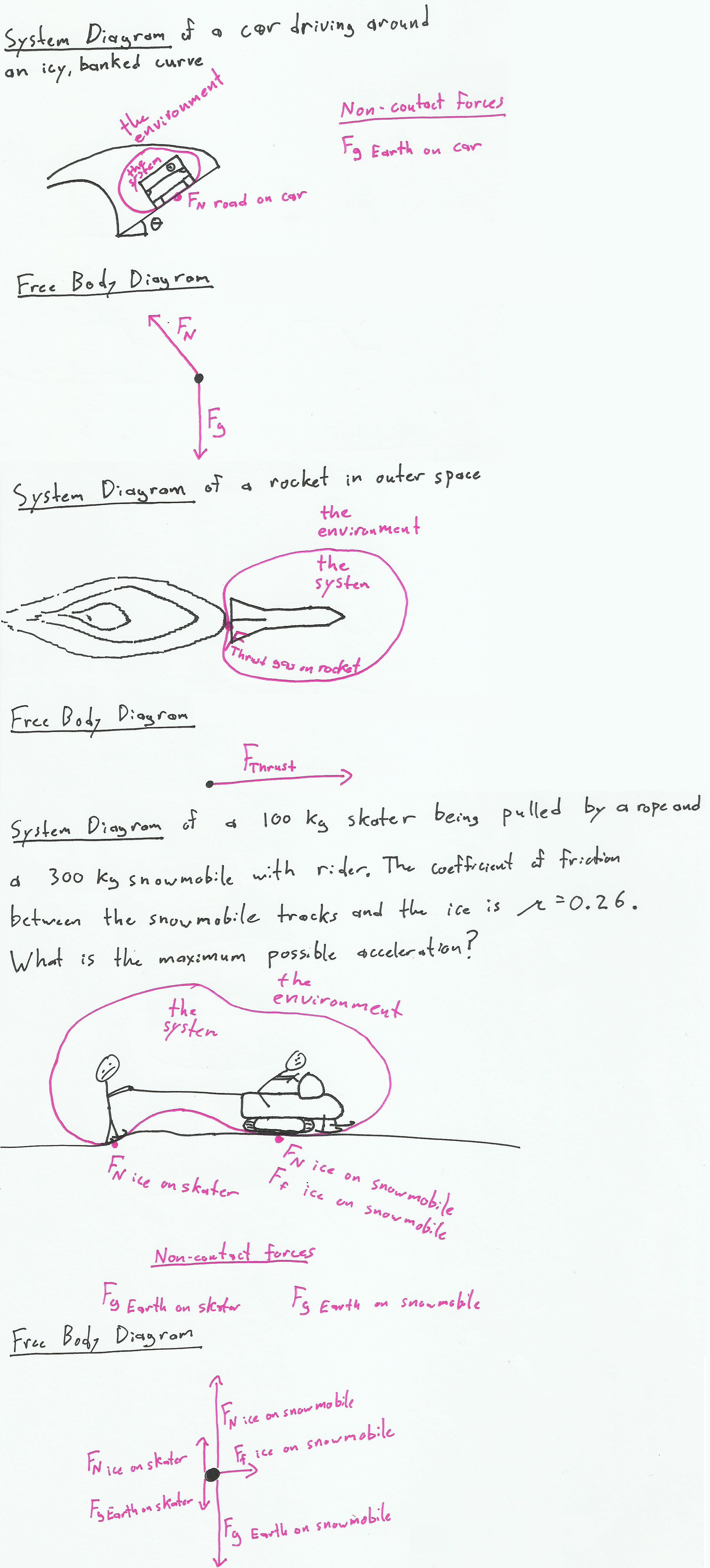
I ask my students to draw their diagrams this way on tests, and I make it worth quite a few marks. This forces students to choose a system of interest and distinguish it from the environment. It forces students to state which objects from the environment exert which forces on the system. It forces students to mention which forces are from contact and which act at a distance. It even forces students to not draw any imaginary forces that arise from an accelerated frame of reference. System diagrams make it obvious what the mass of the system is too, because it’s the mass of everything enclosed by the curve. This also reinforces Newton’s third law; my favourite example involves asking students to draw diagrams of a rocket accelerating forward in outer space, and asking what exactly pushes the rocket forward.
Have Fun with it!
The students love how gifted I am at drawing system diagrams, even though I have no artistic talent and it adds life to what might otherwise be a boring lesson. Also I like to tell the students that drawing these diagrams is extremely difficult. This motivates them to try to draw them to prove me wrong and I believe it to be a true statement anyway. The diagrams are the ‘difficult physics’ after all. After you’re done the diagrams, working the equations is just ‘easy math’. Most of my students seem to think (unfortunately) that math is easier than physics.
Here are some more examples: