Dave Doucette,OCT
Richmond Hill HS (retired)
STEAM Education Consultant, FAST Motion Studios, Toronto
doucettefamily@sympatico.ca
A 2016 paper
1 surveying Purdue University electrical engineering undergraduates discovered “…seniors were more confused than novices about physical concepts such as charge, current and electrical field.” The study did not reveal precise reasons but did caution that well-intentioned but incorrect analogies “usually transform into foggy concepts students carry towards graduation (p4).” This echoed a 2008 engineering-science paper
2 investigating obstacles to concept attainment of direct current. One barrier was weak modeling of the phenomenon, “…and identified the cause of this deficiency as lack of direct experience which can be remediated by creative instructional design.”
The actual mechanism of potential difference and direct current involves surface charge distribution. The challenge to develop this conceptual foundation is its invisible nature. Students cannot directly observe charge and ‘creative instructional design’ is needed to carefully scaffold inferences from static to moving charge. This paper suggests a series of activities to create the experiential background necessary for robust modelling of surface charge distribution. This conceptual foundation will be applied to series and parallel circuits to reinforce Kirchhoff’s laws.
How does understanding surface charge density contribute to equity? According to Carol Dweck
3, a growth-mindset classroom emphasizes understanding of concepts, as opposed to rote memorization, which better engages women, minorities and students of low socioeconomic status. Equity cannot be achieved if students opt out of the education process. Teaching methods which engage disenfranchised students move us along the continuum towards equity.
Static Electricity: neutral, positive and negative charge
An essential first step for students is to concretely operationalize the terms
neutral,
positive and
negative charge. This can be done easily with transparent tape
4. Oppositely charged strands of tape are draped below any convenient surface. Neutral objects are attracted to both tapes while charged objects are repelled by the similarly-charged tape. This tactile experience is essential in an era wherein many students have a restricted experience with the physical world. “Although touch is one of the most fundamental ways through which people interact with the physical world, surprisingly little is used as a vehicle for conceptual learning
5.” It also informs students how inductive reasoning leads to scientific concepts and terminology — in this case, positive, negative and neutral charge states. A simulation does not replace the hands-on experience of working with authentic materials.
At this point the terms conductor and insulator can also be operationalized. An inflated latex balloon is charged negatively with fur/dry human hair at a location on the balloon. Circle the location with a marker and label as (-). This region is strongly attracted or repelled by the transparent tapes. A rotation of the balloon reveals the charge to be localized, as other regions of the balloon are neutral (or far weaker in charge)
6. Students quickly intuit charge is unable to migrate along the balloon surface thereby operationalizing the term,
insulator.
For a conductor, a spherical metal surface is ideal though a flat aluminum pan can substitute. Charge the metal by contact. Rotation of the sphere — held the same distance from the charged tapes — will reveal an equal charge distribution on the spherically symmetric surface, as witnessed by constant attraction or repulsion of the charged tapes. This operationalizes a conductor.
Students need to be encouraged to use words and diagrams to explain the observations on the insulator and conductor (e.g. whiteboarding). However, to try and ensure common visualization, role-playing is invoked. Role-playing allows students to deconstruct and repackage core concepts. In this collaborative environment students discuss and refine terms and concepts, confront misconceptions, and nuance details under-appreciated in a didactic presentation. Multiple representations accommodate students’ different strengths in perception, language, and comprehension.
7 Provide students with two 8.5 x 11 sheets; one labelled as (+), the other (-). Mark out an area on the floor as a sample of a neutral metal outer surface. Students move onto the surface, placing the (+) page on the floor while holding the (-) page. When students move, the (+) charge remains fixed on the floor, appropriate for fixed nuclei in a conductor. Students assume the role of (-) charge (valence electrons) and are mobile on the outer surface.
Students are asked to distribute themselves in a scientifically-reasonable manner and articulate their reasoning (e.g.: we repel each other so we get as far apart as we can, without bunching up). Avoid providing the ‘right’ answers — allow them to reach consensus, even if errors exist. Use Socratic questioning to help them confront and resolve misapplications. This aids in teaching how to think, not what to think.
Introduce scenarios as appropriate, such as:
- bring a (-) charged insulator near the metal surface and allow students to redistribute. This will operationalize induction as the surface does not gain or lose charge but does now have (+) and (-) regions.
- bring a (+) charged insulator near the metal surface and allow students to redistribute.
- repeat a) and b) but change the neutral metal surface by first removing or adding (-) charge. This starts the paradigm with a charged outer surface interacting with a charged insulator.
- separate students into two adjacent outer metal surfaces. Allow student choice as to the charge state of each metal surface. As before, let them achieve consensus and moderate results as needed.
In each scenario, carefully draw out student articulation. The resulting back-and-forth discourse establishes a shared conceptual understanding - even with ‘quiet’ students who prefer to listen. Equity lies within this understanding.
Static to Current Electricity: the LED connection
The most effective method of bridging static to current electricity is through the use of a special LED8. Dim the lights, rub a balloon or any convenient plastic surface with hair/fur and touch the LED to the surface. It will flash briefly. This can be repeated before charge is ‘used up’. Recharging the surface by friction allows the LED to be relit. Note only the rubbed portion(s) of the insulating material causes the LED to light — returning to the operational term of an insulator.
A charged metal surface is then used. The LED will flash brightly and briefly when touched to any part of the metal surface. As before, encourage students to connect these observations with the operational models of insulator and conductor. This observation is consistent with charge instantaneously migrating from all parts of the outer metal surface through the LED at once. In pure fact, it occurs over a few nanoseconds.
Conditions for the movement of charge: surface charge density, δ.
This is a perfect juncture to discuss conditions necessary for charge to move from one conducting surface to another. Students have already inferred an unequal charge distribution as the causative agent of moving charge. An uneven charge distribution can be labelled as electric potential difference (i.e., voltage) without formally defining the term.
Students can act out scenarios in which the electric potential is increased or decreased. The goal is to have students increase potential by cramming more charges onto the conducting surface. Removing charges decreases electric potential in this context.
Reduce the area,
A, of the conducting surface and challenge students to assess the change. Physically this requires (-) students to move closer together, despite their repulsion. In system language, this requires external work to be done on this ‘system’ of charge distribution. The external agent(s) must apply force in the same direction as the charge displacement to arrange them closer. The positive work done by the external agent increases the electric potential energy of the charge distribution.
Varying charge arrangements,
Q, on each conducting surface and changes in surface area,
A, cue students to appreciate electric potential to be associated with charge per surface area,
Q/
A, and electric potential difference as the difference in charge per surface area, ∆(
Q/
A). This models the process scientists use to define conventional terms such as ‘charge per unit area, i.e., surface charge density, symbol, δ.
The stage is set to properly understand electric potential difference in terms of the actual mechanism of surface charge density. Students should be able to articulate the need for a difference in electric potential between two surfaces as the precursor for moving charge. A conductor placed between surfaces allows for charge to move until the surface charge density is equal on both surfaces.
Allow students to role-play moving charge by joining two unequal charge density surfaces with a conductor. Students can freely move across this conducting ‘bridge’ until the surface charge density is equalized. Charging by contact (via sparking) can also be modelled by students leaping across a gap between surfaces — if the electric potential is high enough, i.e. charges crammed very tightly!
Conditions for Electric Current: batteries
What is necessary for continuous charge flow, as in DC electric lighting? How do we maintain a steady potential difference once charge begins migrating? A simple battery powering a light bulb is evidence of a steady-state current. To help reveal the mechanism, students could build a lemon cell battery. The internet is rife with examples
9. Continuous lighting indicates a steady supply of electrons through the light. If the light were to dim, the flow of electrons must have diminished. If brighter, they have increased. These inferences are consistent with the conceptual model so far developed.
Applying the Model to Circuit Analysis
To prepare student thinking for application to circuits it is helpful to expand on the simple light bulb example. Rather than wiring the battery directly to the light bulb, attach the leads from the battery to two aluminum plates. The light bulb can now be lit by touching it across any two points across the aluminum plates. No matter where it connects, the bulb has the same brightness compared to direct wiring with the battery. A voltmeter will verify the same potential difference across any two points on the plates. Constant illumination indicates a steady-state current. Plates can be replaced by smaller aluminum (or other) strips until the analogy to wires is clear. This simple, concrete experience anchors robust mental modelling for surface charge density as the causative agent of current and a battery as a steady-state charge source. Misconceptions in these areas are well documented, even amongst electrical engineering graduates
11.
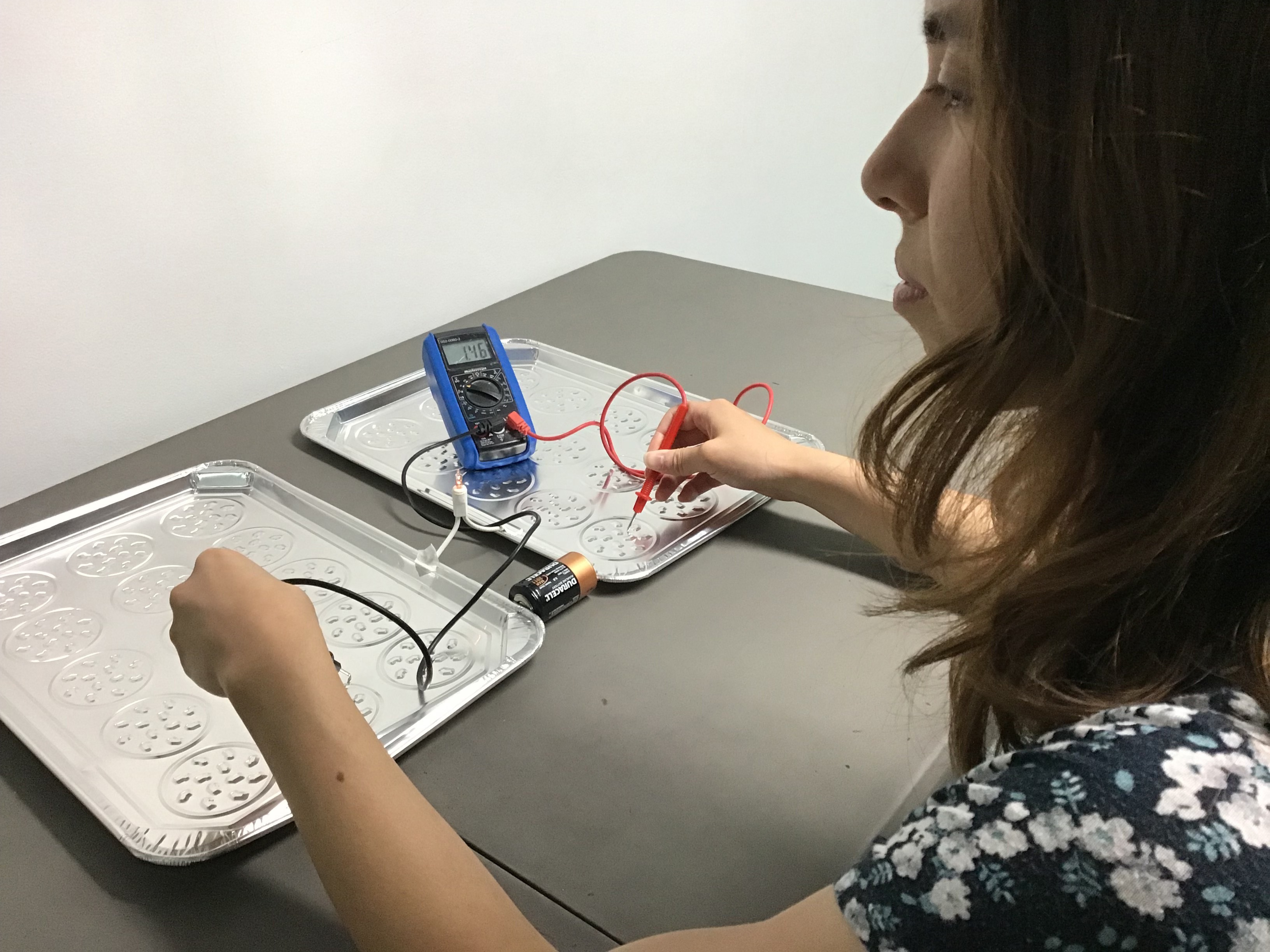 Photo 1: The battery source has both electrodes pressed against aluminum cookie plates (conductors). The reading on the voltmeter (1.46 V) is constant wherever the student places the electrodes across plates. This infers uniform surface charge density across plate surfaces.
By extension, the potential difference between any two points across the two conducting wires in a circuit would also be the same. If bare metal wires are used, this inference can be verified. Careful questioning will help students articulate equal surface charge density on the aluminum plates, the conducting wires and the battery terminals to which they are connected.
Using Surface Charge Density in Circuit Diagrams
The developing visualization of surface charge prepares students to apply the model to electric circuits. A series of pictorial diagrams helps with this contextualization. The first diagram of a simple ideal circuit shows the wires at the same potential as the battery terminals, as described above. The potential difference across the load is the same as the battery.
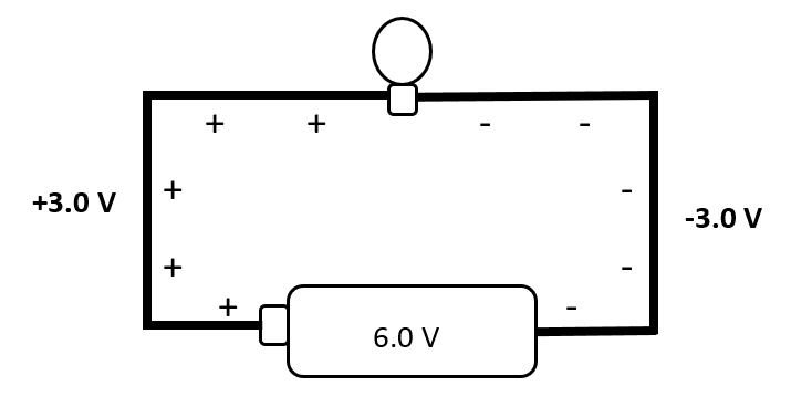 Diagram 1
A significant question is where the 0.0 V value would lie in this charge depiction? It is exactly midpoint on the (uniform) nichrome resistor of the ‘old-school’ incandescent bulb. This resistor is drawn with a uniformly changing gradient from -3.0 V to +3.0 V, end to end, as shown in the illustration below:
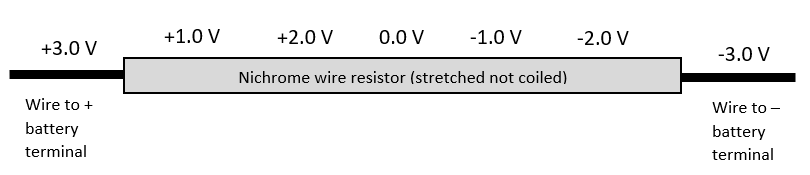 Diagram 2
Scaffolding from a simple circuit to series and parallel circuits is achieved by pictorial representations. A two-load series circuit continues the ideal wire scenario and adds a conducting wire between identical loads, as seen below.
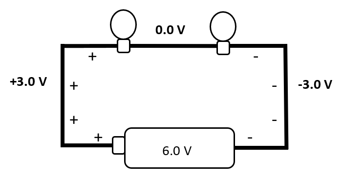 Diagram 3
Charge distribution across the loads is gradient-driven but along the (ideal) connecting wire it is uniform. If the load resistances are identical, the conducting wire between the loads will be midway in surface charge density, 0.0 V. This conforms to Kirchhoff’s laws regarding the sum of potential differences across the loads equaling the potential difference across the battery. The classic mathematical approach is now solidly anchored by conceptualizing surface charge distribution.
If the loads had unequal resistance, the charge distribution would adjust. If, for example the region between loads obtained a voltage of -1.0 V, it would correspond to potential differences of 4.0 V and 2.0 V, resulting from resistances of 4.0 Ω and 2.0 Ω, as in the diagram below.
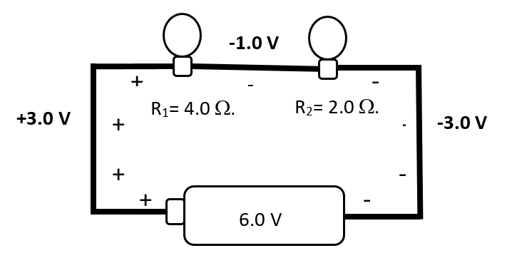 Diagram 4
Easy Parallel Circuit Analysis
Parallel circuits are also simple to interpret, whereas traditional mathematical treatments can cause confusion. Understanding charge distribution allows for mathematical treatment of the paradigm together with robust visualization. Recent brain research reveals, “When we work on mathematics, in particular, brain activity is spread out across a widely-distributed network, which include two visual pathways… mathematical thinking is grounded in visual processing
10.”
Diagram 5 shows three identical resistors in parallel. Charge distribution along the wires is the same as the connected battery terminals, leading to a potential difference of 6.0 V across each load. This indicates an equal current through each resistor and the total current as the sum. If the resistance of each load was
R = 3.0 Ω, the current through each would be
I = 2.0 A, with a total current,
IT = 6.0 A. Ohm’s law stipulates the total resistance of the circuit as the ratio of voltage/current:
RT = 6.0 V/6.0 A = 1.0 Ω. This, of course, is the same result as Ohm’s equation for equivalent resistance.
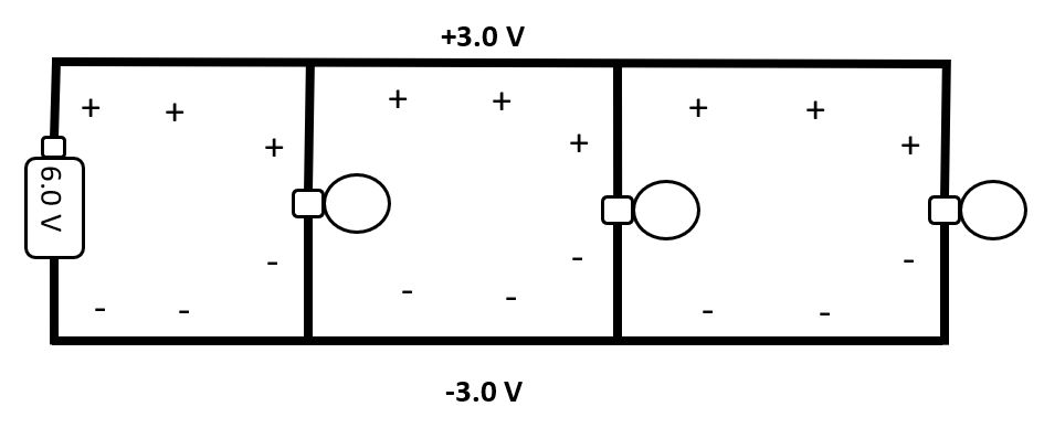 Diagram 5
Unequal resistors are equally simple to analyze, beginning with identical potential differences across each load as above. Clearly the current in each loop will vary, inversely to the resistance. The result for total resistance of the circuit RT yields the inverse law for equivalent resistance with multiple resistors in parallel. Being able to visualize the charge distribution augments the mathematical formalism.
Scaling up to combination circuits will likely require application of Kirchhoff’s and Ohm’s laws to establish potential differences before a surface charge distribution diagram could be completed. It would be advisable to have students sketch a surface charge diagram to recognize the combination context is still understandable pictorially. However, the mathematical base provides necessary values for potential difference when a circuit is complex. This helps affirm the value of mathematical formalism with increasingly complex phenomena.
Approaching Equity through Understanding
The ideas presented here require a modicum of equipment for a scaffolded approach to potential difference and current, which research reveals are poorly understood even among physics and engineering students. The correct mechanism of surface charge density is accessible through guided-inquiry static-to-current treatment. The unseen charge becomes almost palpable as mental models evolve to explain and predict. This mirrors the scientific mindset of experts who articulate scientific models. Predictions are tested through experimentation and theories refined based on the dictates of evidence.
Role-playing provides opportunity for students to discuss, refine and consolidate observations into a shared model of charge distribution, laying solid groundwork for richer analysis. Further, the interactive nature of role-playing engages students who may not flourish in a traditional didactic treatment. The abstract nature of charge is made accessible though inferences anchored in experience with concrete manipulatives.
Teaching through differentiated mathematical, visual and social-interactive methods engages more students thereby establishing a more equitable classroom culture. Diverging from the traditional treatment is risky, so give yourself permission to make mistakes in the process. Have a sense of humour and humility. We are equally students of physics, just further along the continuum of learning. Physics, artfully prepared, should be enjoyed not endured.
Editor’s note: Dave presented this topic at the 2019 OAPT Conference. The slides Dave used in this presentation will be available on the OAPT website.
References
- Tatiana V. Goris Purdue University, Common Misunderstandings of Electricity: Analysis of Interview Responses of Electrical Engineering Technology Students; International Journal of Engineering Pedagogy ‒ Volume 6, Issue 1, 2016, p8.
- Streveler, R., Litzinger, T., Miller, R., Steif, P; Learning Conceptual Knowledge in the Engineering Sciences: Overview and Future Research Directions; Journal of Engineering Education, July 2008, p291.
- Carol Dweck; The Remarkable Reach of Growth Mindset; Scientific American, Special Collector’s edition, Winter 2019.
- There are numerous scotch (sticky) tape videos available. One example is: https://www.youtube.com/watch?v=wkBG821cvLU .
- Alzayat, A., Hancock, M., Nacenta, M.; Quantitative Measurement of Virtual vs. Physical Object Embodiment through Kinesthetic Figural After Effects; CHI 2014, One of a CHInd, Toronto, ON, Canada, Session: Multitouch Interaction, p2903-2912.
- Uzma A. S., Shaikh,Alejandra J., Magana, Luis, Neri,David, Escobar-Castillejos, Julieta Noguez and Bedrich Benes; Undergraduate students’ conceptual interpretation and perceptions of haptic-enabled learning experiences; International Journal of Educational Technology in Higher Education. 2017, 14:15
- Balloon materials are usually charged by incidental contact. To neutralize surfaces, a slightly dampened towel can be used to gently stroke the surfaces. Allow to dry thoroughly before testing for neutrality.
- Ontario Ministry of Education, Learning for All, 2013, p 16.
- The author obtained these LED’s from Steve Spangler Science, www.SteveSpanglerScience.com in 2007. The product title was “Static Powered Neon Light.” This type of LED was sold at Radio Shack in the early 1990’s and discontinued. It is not known if Spangler Science is still offering the items for sale.
- Lemon cell batteries to light LED’s. https://www.youtube.com/watch?v=TQHS509_0so
- Boaler, J., Chen, L., Williams, C., Cordero, M.; Seeing as Understanding: The Importance of Visual Mathematics for our Brain and Learning; Journal of Applied & Computational Mathematics, Vol 5 Issue 5, 2016.
- Goris, T; Common Misunderstandings of Electricity: Analysis of Interview Responses of Electrical Engineering Technology Students; International Journal of Engineering Pedagogy; Vol 6 No 1, 2016
Tags: Diversity, Electricity, Pedagogy