Philip Freeman, teacher at Richmond Secondary School (Richmond BC), Executive member BCAPT
freeman@sphericalcows.net
Waves are the source of many of the most beautiful and fascinating phenomena in physics, and a key idea underlying our deepest models of reality. The signature feature of waves is interference, and we frequently refer to interference effects to justify our claims about the wave nature of light (and electrons, and buckyballs, and…). This resource provides a new way to model waves that allows a more direct and intuition-building experience of interference.
The interference of waves is a very abstract and difficult idea for many students and for some time I have attempted to find a simple hands-on model for waves that clearly showed this concept. One good attempt at this involves printing sine waves on transparency, but the result still requires quite a bit of interpretation.
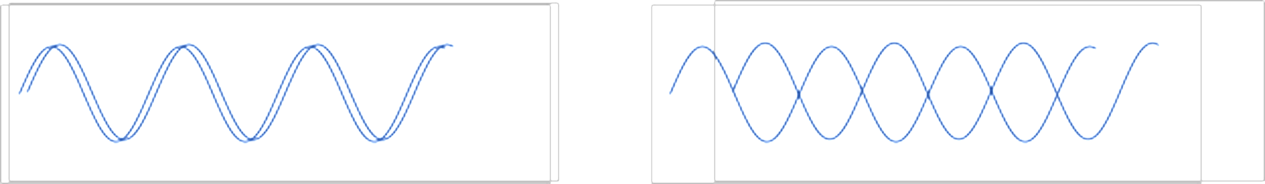 Figure 1: Constructive and destructive interference
The density of a gradient allows for a much more intuitive wave overlap and spreadsheets provide a very easy way to construct such a printout. Here are examples showing constructive and destructive interference.
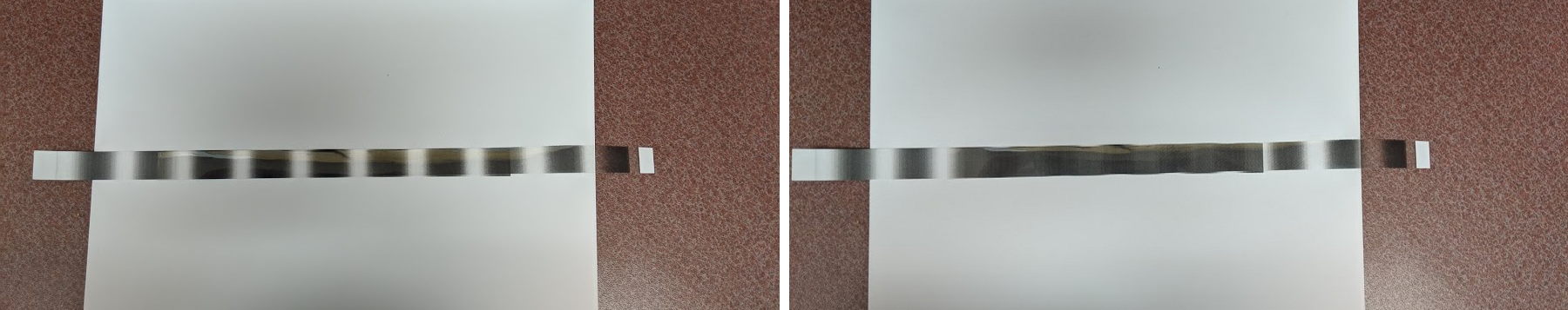 Figure 2: Constructive and destructive interference
The transparency is printed with a density of grey to represent the amplitude, from clear (a trough) to about 40% dark (a peak). Overlapping two crests then produces a more intense region, while two troughs remain clear. A crest on a trough produces a uniform grey. Since the shading is done according to the amplitude, intermediate forms of interference are also modelled reasonably well.
Students can quickly observe while playing with the waves that constructive interference happens when one wave is displaced a whole number of wavelengths, and destructive for ‘half way’ points. A few simple exercises show the criteria for constructive and destructive interference in this intuitive way.
Examples
Several quite useful interference effects can be observed using these models. For example by combining waves of different wavelength beats can be observed:
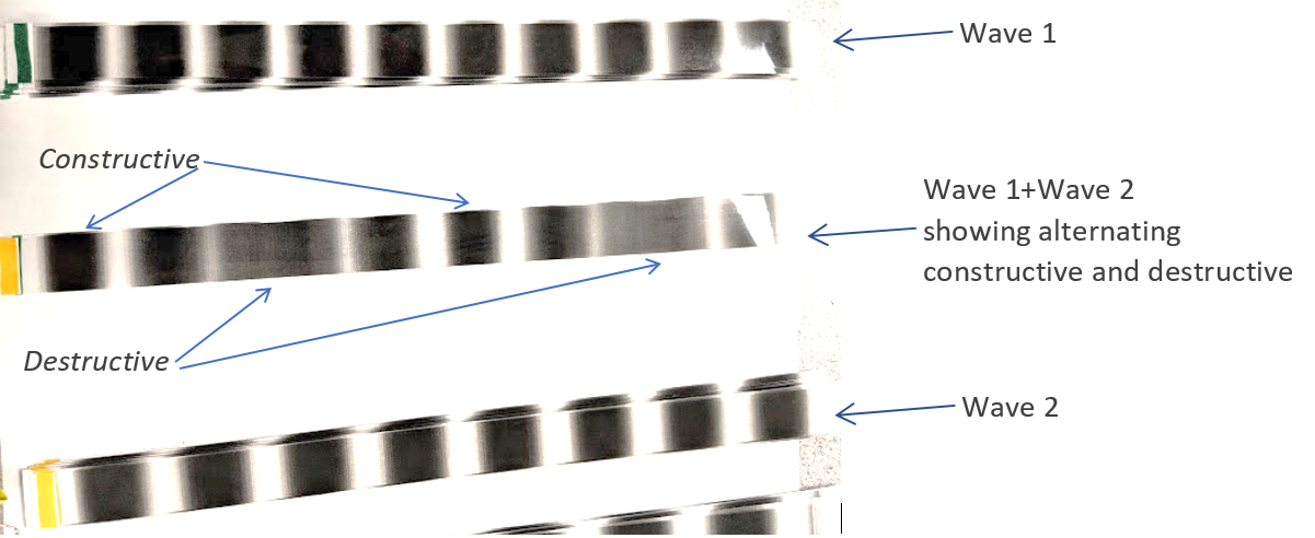 Figure 3: Beats
Circular waves can printed as well, and used to investigate double slit interference (I will provide a short article on a classroom activity based on this separately):
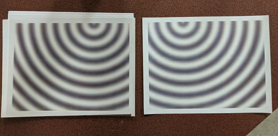 Figure 4: Circular waves (here one wave is on paper to reduce cost, the other is on transparency — the transparency is flipped)
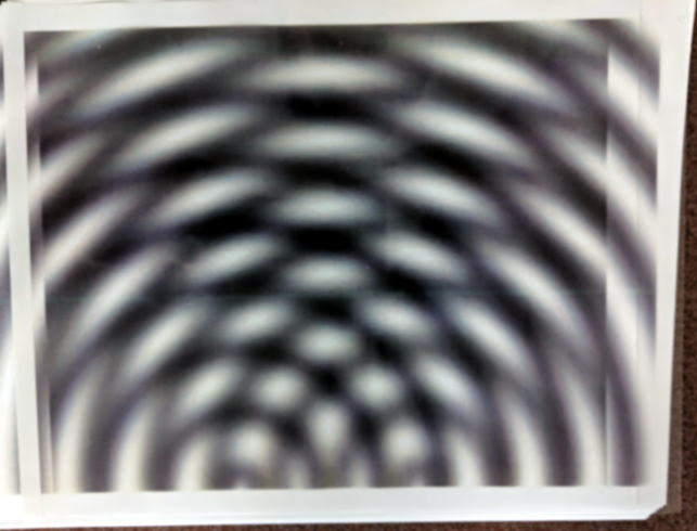 Figure 5: Circular waves combined to investigate two slit interference
The Spreadsheet
Accompanying this article is a zip file with the wave generator and three PDFs of waves for those who might not have Excel but want to try the model. The spreadsheet uses Excel conditional formatting to produce wave images of adjustable type, wavelength, phase, and origin. There are two sheets, one of which has the ‘controls’ to produce the waves you want (“Settings”), and the second sheet/tab is the one to print (“Image”). The image sheet must be printed at reduced size. It prints on 8.5” × 11” North American standard paper at 11% (which should be preset). At this scale 1 unit is about 2.8cm (1.1 in).
The settings allow you to specify a wavelength (in the semi-arbitrary units of the image sheet) and a phase (in degrees). You may specify either circular waves (type 0, because that’s kind of circular?) and plane waves (type 1, because… you get it.) The options presented change to fit the type of wave chosen.
These waves are produced on the same grid, so the wavelengths remain the same and plane waves and circular waves with the same wavelength settings will print with the same wavelength (very handy for making links between the two!)
If you choose circular waves you may specify the waves centre. If you choose plane waves you may choose waves moving in the x-direction (along the long side of the paper) or moving in the y-direction (along the short side). The sheet is defined in landscape orientation, with x-values ranging from -4.8 to +4.8 (zero centred) and y-values from 0 to 7.3 top to bottom (admittedly inconsistent, feel free to change it as you wish). The values correspond very roughly to inches on the printout, but only very approximately. I have made no attempt to be more precise as different printers will scale things slightly differently in any case!
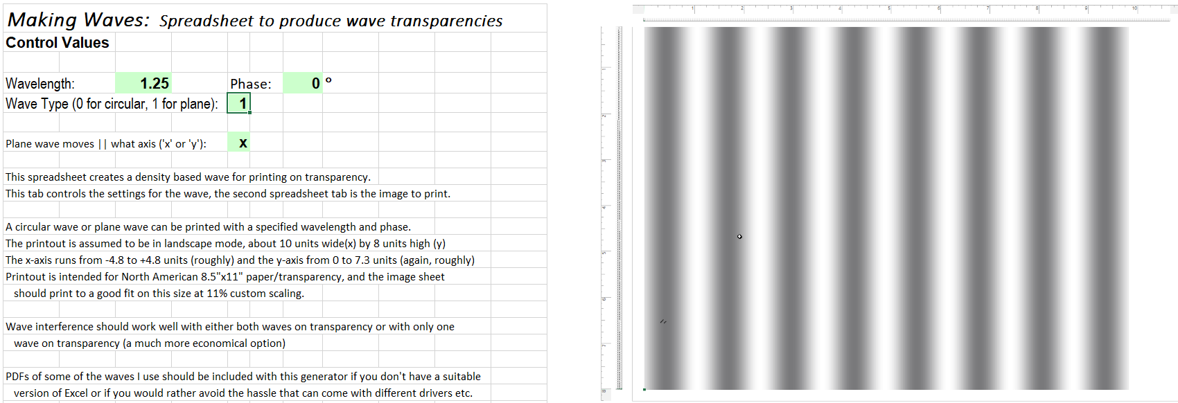 Figure 6: Spreadsheet for linear waves
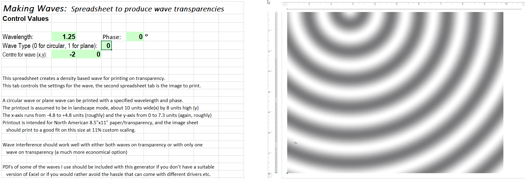 Figure 7: Spreadsheet for circular waves
Plane waves are intended to be cut into strips (as seen in previous images). I find that about 1 to 1.5 centimetre (or around half an inch, whatever your paper-cutter makes easy) are about right. Too narrow and the interference is not so striking. Too wide and the strips don’t bend well (and things are more expensive!)
Print the waves directly to a laser or inkjet printer with suitable transparency. Try some prints on plain paper first to adjust the settings, and see if your printer has a transparency ‘paper’ setting! I print copies on transparency and an equal number on paper, since in many situations only one wave needs to be transparent and this saves a lot of expense!
If longer wave strips are needed the strips can be glued to make longer strips, but you need to be careful with what glue you use. I have spent quite a bit of time trying different things before finding some that work! The best I’ve found is unfortunately not super-available, it is canopy glue intended for RC model airplanes (I used “Formula 560 Canopy Glue”). I am currently trying a less tricky to obtain glue (Weldbond) from my local hardware store, which many folks on the sites for those RC planes swear works for their purposes. I haven’t had enough time to see if this ages well, but it seems to hold for a while at least! Apply the glue with a small brush over a fairly large area of the strip (at least a couple of cm overlap taking care to align the waves properly. The glue will smudge the print, so try to glue the sides without ink!
Here are some things that don’t work (or didn’t work for me when I tried them):
- acetone (or acetone dissolved bits of transparency… this is what would usually work for acrylic but transparency plastic does not dissolve at all, so it does not behave like acrylics I am used to)
- ‘crazy glue’ or other cyanoacrylics (these don’t adhere well and break when flexed)
- white glue (Hey it was worth a try)
- craft glue (‘Tacky glue’), epoxy… these all refused to adhere for me or broke when used.
- double-sided tape for scrap-booking
To get the waves straight and coherent I have tried aligning with rulers etc. but it seems best to simply place another wave strip alongside the two you are gluing (as shown below), so you can position accurately by eye. The glue is loose for some time and minor adjustments can be made. Make sure you get the ends of both strips!

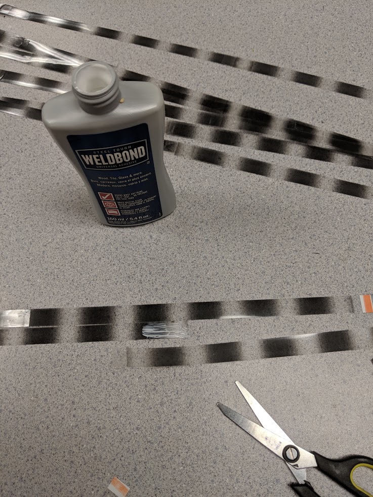 Figure 8: Assembly of strips
It takes a couple of days for the glue to dry to a clear form, and it isn’t perfect, but it works!
A Further Example: Intro to thin film interference
Long wave strips can be used to model interferometers or thin film interference by using pegs to “reflect” the wave (finishing nails in a board for example). Waves simply wrap around the peg and return, albeit with a very small shift in phase but this is generally negligible. A carefully chosen post or dowel, in fact, can even introduce a half wavelength phase shift on “reflection” (I have done this by wrapping paper strips and tape around a post to get the right thickness for the effect). Of course care must be taken to point out that this is not a good analogy for how actual reflection of waves occurs if one is trying to get clever this way!
I would start with the simple but crude model I show below, then introduce the effects that modify the model to better reflect the real complexity (change in wavelength in the film, refraction entering and leaving, phase changes)…

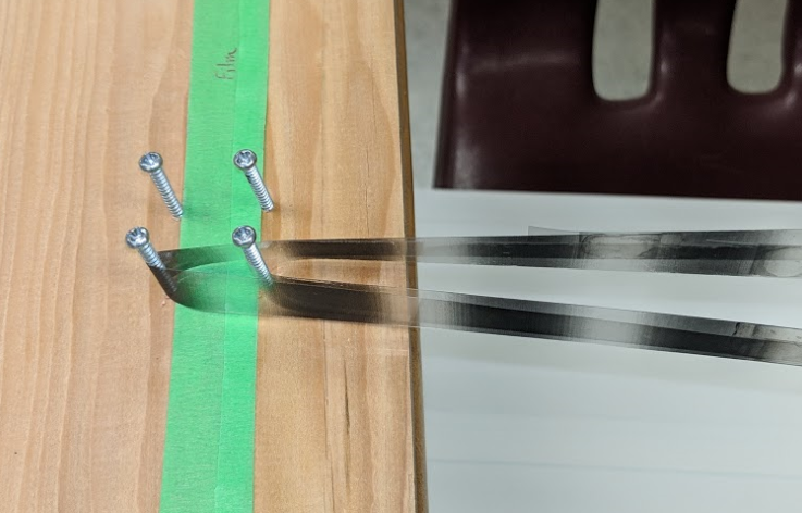 Figure 9: Thin film interference — reflection from a wave reflecting ‘straight back
Thin film interference with thickness about ½ wavelength for this wave, giving constructive interference of the two reflections. A strip of coloured masking tape is used here to represent the film with reflection from front and back of the film.
Reflection of the same wave from the same film, but at an angle (waves enter from the top right). Now the two reflected waves give destructive interference:

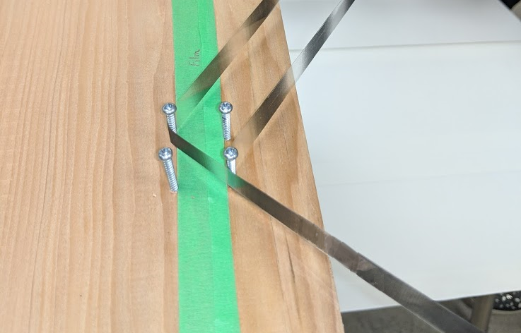 Figure 10: Thin film interference — reflection at an angle
A follow-up article will show a resource using these models to investigate double slit interference. Many other activities are possible.
I hope you find this wave model useful. The spreadsheet to generate the waves and some prepared PDFs can be downloaded
here. Please let me know what amazing things you end up doing!
Tags: Light, Waves and Sound