December 24, 2021 Filed in:
ArticlesAdam Mills
President, Ontario Association of Physics Teachers
Assumption College Catholic High School
adam_mills@wecdsb.on.ca
This article continues from the
initial article I wrote on optics, which detailed many of the misconceptions that students struggle with but are hidden inside the simple mathematics of the unit. In this article I look at practical ways for making the optics unit more interactive, with a focus on developing the rules for ray diagrams and the cooperative group problem solving I have my students complete at the end of the unit.
In order to make this unit as hands-on as possible, groups of students need access to a ray box, a flat double concave lens, a flat double convex lens, a laser pointer and a semicircular lens (Figure 1). I am not going to go into detail about each inquiry-based lesson that I complete; however, you can find them
here. Furthermore, the Perimeter Institute has recently dropped a new series of lessons around Optics that you can find
here.
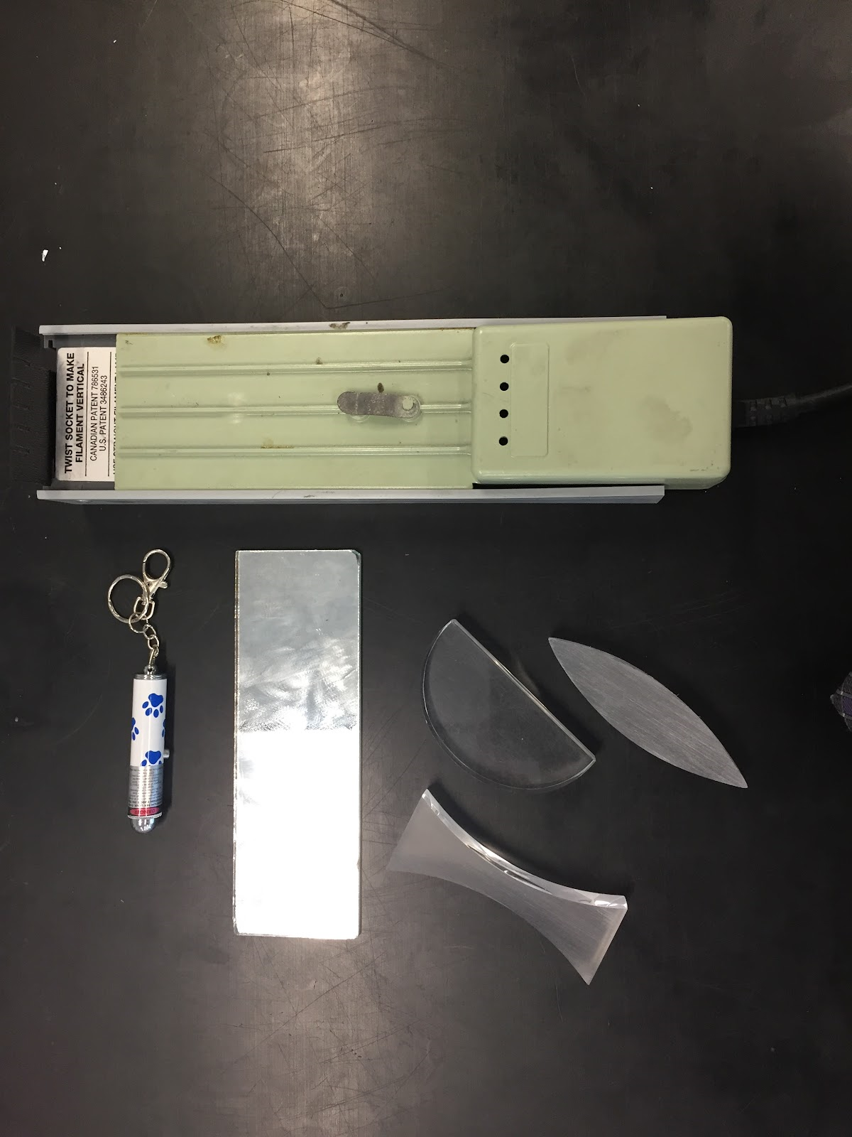 Figure 1: Basic equipment required for each group.
After you have established how the eye actually sees an image (first article), one of the next crucial steps is to establish the rules for creating ray diagrams. Oftentimes in textbooks, the rules are simply stated with the aid of a diagram similar to the one shown in Figure 2.
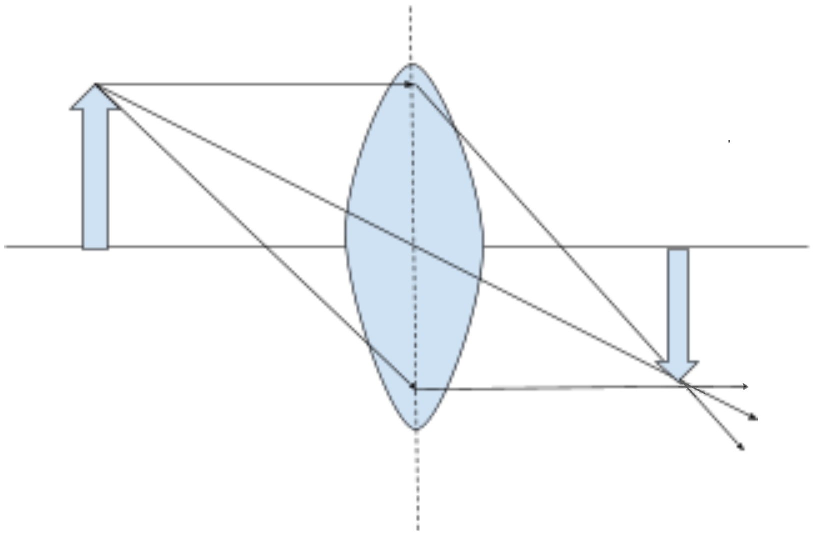 Figure 2: Standard textbook diagram demonstrating a ray diagram.
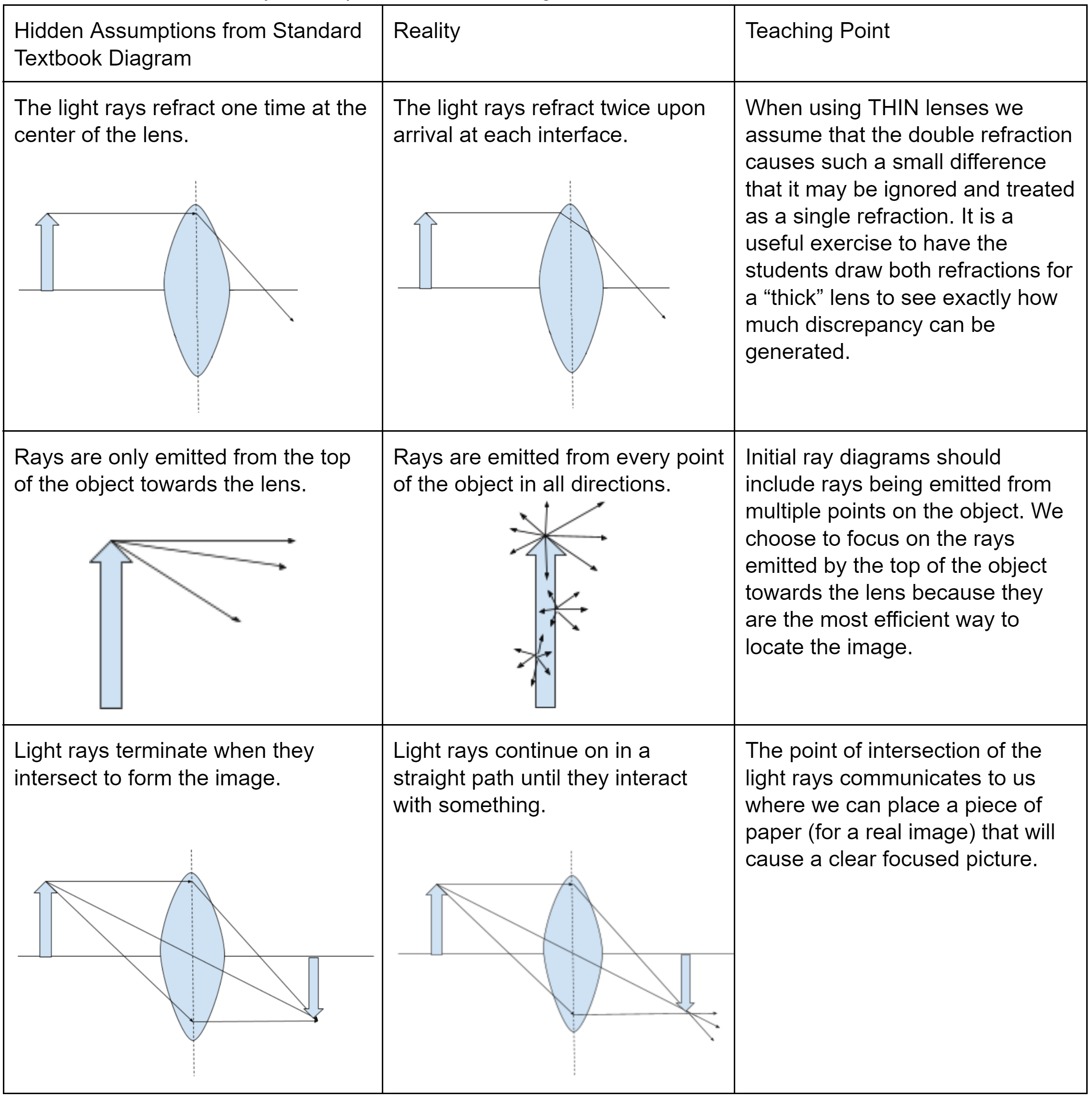
The problem with the standard ray diagram is that it is filled with hidden assumptions and shortcuts that we experts take for granted. Our job is to make sure that we explicitly highlight these assumptions and shortcuts to the students in order to fully develop their understanding.
I was fond of the
PhET Geometric Optics Resource; however, as of publication they have yet to make it available for HTML 5. Luckily there is still a good simulation software I like called “Ray Optics” as an extension for Google Chrome, which can be found
here.
Using this software, students can develop the three ray diagram rules found
here with some guidance. For example, they can observe what happens when a beam of parallel rays passes through a double convex lens (Figure 3). My only complaint is that this simulation does not show the lens, but rather represents it with arrows at the top and bottom. Although I point out to the students that it is making the thin lens assumption by drawing the lens with no thickness!
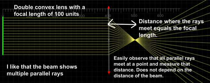 Figure 3: Ray diagram of a parallel beam passing through a double convex lens.
At this stage the students should be able to determine that parallel rays sent into the lens will converge at a point that corresponds to the focal length of the lens. However, we need to establish that
only parallel rays refract through the focal point; this is often overlooked. To accomplish this, I have the students use a point source and observe if they can create any situation in which a single ray will
always pass through the focal point (Figure 4).
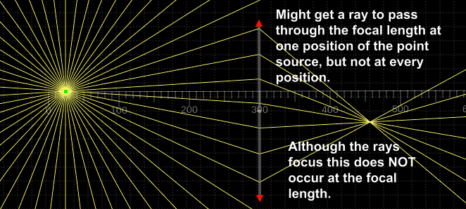 Figure 4: A point source passing through a double convex lens.
The combination of these two ideas allows students to establish that rays that are parallel to the principal axis will
always pass through a point located at the focal length of the lens.
Similar scenarios can be used to establish the other two ray laws. We then need to convince the students that with these three ray laws, we can determine where an image will be located by finding the place where these three special rays converge.
The unit culminates with a cooperative group problem solving (CGPS) question. In this CGPS question the students are given a randomly drawn double convex lens from a bag and asked to magnify a drawn image by a randomly assigned amount between 4X — 8X and have it appear in the correct orientation. I have found that asking for a magnification any bigger than this reduces the quality of the image. They are shown the following setup (Figure 5), which requires an old overhead projector! I have taken the overhead projector and removed the lens assembly so it simply acts as a light source. It needs to be made clear that the projector can move. The students then draw a picture on overhead paper and must work through the problem to determine the relative distances between their lens, the overhead/image and the screen to produce an image of desired size.
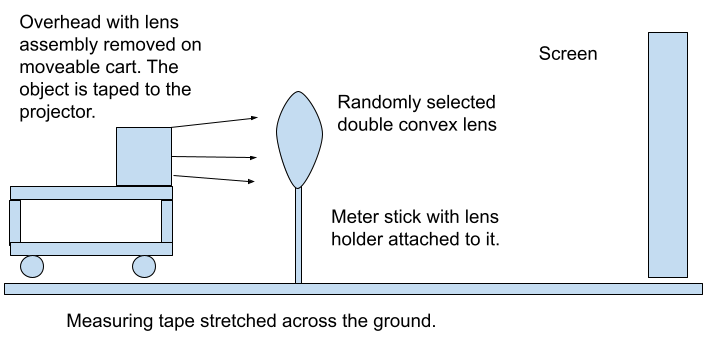 Figure 5: Setup for the cooperative group problem solving question.
Some important notes, the students are not allowed to use the setup in Figure 5 until they are ready to test. They do have access to the other equipment in the room (candles, optics bench, etc.) in order to determine the focal length of their lens. They also need to realize that they must attach their drawn picture upside down in order to ensure it appears right side up on the screen. An important teaching point is that the lens may need to be adjusted horizontally so the image appears on the screen. Only after they have placed their image and positioned their lens do we turn on the projector, then by measuring the original dimensions of their drawing and comparing it to the created clear image, the students can assess if they have properly completed the task.
After completing this inquiry-based unit for optics a couple of times now, I have found that the students have a much clearer understanding of how geometric optics works. If you carry out this activity in your classroom and have any feedback or suggestions for improvement, feel free to contact me at the email address listed above.
Tags: Optics, Pedagogy